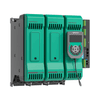
Control of the electric heaters of the float systems with electronic power controller
Find out how in the cooling tunnel of a float glass plant the electronic power controller allows you to control the electric heaters based on the temperature profile and the cooling gradient
The cooling tunnel is a critical section in the float glass production process
This phase must be cooling controlled (hot to cold) to avoid any cracks on the glass sheet due to an incorrect temperature gradient. GPC three phase power controller is used to:
- control resistive heaters;
- provide various diagnostics including heaters break alarms, line voltage, protection fuses and overall health of the power controllers;
Overview
- Annealing Lehr is one of the important processes in a float glass plant (see Figure 1). The objective of Lehr Kiln is annealing and to avoid cracks on the glass sheet due to temperature gradient
- Simultaneous heating/cooling control is essential to maintain the gradient suitable to the characteristics of the ribbon glass
- GPC 3 PH power controller is used to control resistive heaters and provide various diagnostics including heaters break alarms, line voltage, protection fuses and overall health of the power controllers
The process
Float glass is a sheet of glass made by floating molten glass on a bed of molten metal, typically tin. This method gives the sheet uniform thickness and flat surface.
Float glass is made out of common glass-making raw materials, which is first mixed in a batch process then fed into a furnace where it is heated to approximately 1500 °C (2732°F). Once molten, the temperature of the glass is stabilized to approximately 1200 °C (2192°F).
The molten glass is fed into a “tin bath”, a bath of molten tin (about 3–4m / 13-13ft wide, 50m / 164ft long, 6cm / 2.36in deep), from a delivery canal. The glass flows onto the tin surface forming a floating ribbon with perfectly smooth surface, while the temperature is gradually reduced from 1100 °C until at approximately 600 °C (1112°F).
The glass ribbon is pulled off the bath by rollers at a controlled speed and passes through a Lehr Kiln for approximately 100 m (328 ft). Where it is cooled gradually so that it anneals without strain and does not crack due to change in temperature.
On exiting the “cold end” of the kiln, the glass is cut through glass cutting line.
The challenge
The objective of Lehr Kiln is to reduce the temperature from 600°C (1112 °F) down to 70°C (158°F). Gradient control depends on the characteristics of the glass under production.
For the accuracy of the gradual cooling control, special heat/cool algorithm is required. Heating is done through resistive heaters.
Typical life of a float glass line is 15 years with very few planned shutdown – this calls for robust and maintenance free control equipment.
The control system should command the Power controllers to drive the electrical heaters according to the temperature profile and cooling gradient requested.
The power controllers should drive resistive heaters and be able to provide diagnostics to support preventive maintenance and avoid failures.
Product benefits
Series GPC
- Range: 40A to 600A single/two/three phase
- Easy and flexible configuration by GF_eXpress configuration tool
- Portable display for local access of data and simple configuration by selecting past recipe.
- Self-learning heater break alarm
- Firing mode: configurable
- Connectivity: most common Fieldbus ethernet
Various Diagnostic and Predictive maintenance
- Continuous temperature monitoring of power terminals of the controller via 12 embedded thermistors
- Heater break alarm and customised power control strategy for continuous power to heaters
- Monitoring of line voltage, line frequency, load current, load impedance and load power
Solution
In a specific case, the Lehr Kiln required 16 heating zone in 3 phase configurations.
Total of 16 Power controllers GPC 3 PH have been applied with different current range, for a total load of 2MW (Figure 2).
The power controllers are connected to the DCS Control system via Modbus TCP and analogue signal. In order to allow a safe switch between auto (command from DCS) to manual (command from local potentiometer) operation, like in case of local maintenance, analogue signal (4.20mA) is used as reference power demand (Figure 3).
Through Modbus TCP comms, GPC provides the following diagnostics status to DCS:
- Full and partial heater break alarms (Figure 4)
- Voltage-current-Power value on the load
- State of the on-board fuses
- Over temperature of the Power terminals of the GFW, that can be caused by a poor wiring cable to the power terminals of the GPC (Figure 5).


